Fig. 1: Locations of the tracking stations FT1..FT6 with respect the PANDA dipole magnet.
Forward Tracker
Contact: Jerzy Smyrski
The Forward Tracker (FT) is designed for momentum analysis of charged particles deflected in the field of the PANDA dipole magnet. The FT covers angular acceptance defined by the aperture of the magnet equal to ±10° horizontally and ±5° vertically with respect the beam direction. The momentum acceptance extends above 0.03·pbeam, where the dependence on the beam momentum pbeam is due to the fact that the field in the dipole magnet is scaled according the beam momentum. FT consists of three pairs of planar tracking stations: one pair (FT1, FT2) is placed in front, the second (FT5, FT6) behind the dipole magnet and, additionally, the third pair (FT3, FT4) is placed inside the magnet gap in order to track low momentum particles hitting the magnet yoke (see fig.1).
With expected position resolution of σ=0.1 mm per detection layer and the material budget in one tracking station of 0.3%·X0, the momentum resolution is better than 1%. The tracking stations should stand high local particle fluxes in the order of 104 cm-2s-1 in the vicinity of the beam pipe as well as a high total counting rate of about 2·107 s-1 expected in the high luminosity mode with the number of antiproton-proton interactions of 2·107 per second. The average track multiplicity in the FT is about 1 per event.

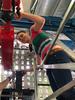
Fig. 2: Mounting of a module on support frame (a), two double layers assembled on support frame (b).
The FT is based on 10 mm in diameter straw tube detectors of the type proposed for the Central Tracker. The straw tubes are made of 30 μm aluminized Mylar foil and are grounded. For anodes 20 μm gold plated tungsten wire is used. The gas pressure inside the straws equal to 2 bars stabilizes the straws mechanically and maintains the tension of anode wires at the level of 50 g. In order to minimize the aging effects, usage of 90% Ar + 10% CO2 gas mixture is considered.
The detection planes are built of separate modules, consisting of 32 straws arranged in two layers. Each module is equipped with its own preamplifier-discriminator card. It has also its own high voltage supply and gas supply lines. In this way it constitutes an autonomous mechanical and electrical unit. Straw modules mounted side by side on support frame form a detection plane which we call double-layer. A module can be mounted and dismounted from support frame without the need to remove the neighboring modules. It simplifies the assembly and repairs of the tracking stations (see fig. 2a). One support frame is used for two double layers (see fig. 2b).
Each tracking station consists of four double-layers: the first and the fourth one contain vertical straws (0°) and the two intermediate double-layers - the second and the third one - contain straws inclined at +5° and -5°, respectively. The planned configuration of double-layers allows to reconstruct tracks in each pair of tracking stations separately, also in case of multi-track events. Basic parameters of individual tracking stations including number of modules and of straw tubes, as well as distance from the target and extension of active area are given in the table 1. The presented numbers might change since the optimization of the FT is still going on.

Fig. 3: Tracking station FT6.
| Station | #modules | #straws | z-pos. [mm] | Area x×y [mm2] |
|---|---|---|---|---|
| FT1 | 4×8 = 32 | 1024 | 2954 | 1298×640 |
| FT2 | 4×8 = 32 | 1024 | 3274 | 1298×640 |
| FT3 | 4×12 = 48 | 1536 | 3945 | 1944×690 |
| FT4 | 4×12 = 48 | 1536 | 4385 | 1944×767 |
| FT5 | 4×25 = 100 | 3200 | 6075 | 4045×1180 |
| FT6 | 4×37 = 148 | 4736 | 7475 | 5984×1480 |
Table 1: Number of modules and of straw tubes in individual tracking stations, position along the beam direction downstream the target (z-coordinate) and the horizontal (x) and vertical (y) extension of active area of the first double layer in each tracking station. The total number of straw tubes in the FT is 13056.
Supports of the tracking stations FT1, FT2, FT5 and FT6 consist of rectangular chassis made of steel profiles and of two pairs of c-shaped frames called drawers which are connected to the chassis with telescopic rails (see fig. 3). One pair including the left and the right drawer is used for supporting two double layers. The drawer can be moved in the direction perpendicular to the beam pipe allowing for an easy access to the straw modules also in the case of tracking station installed in the experimental position.

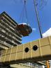
Fig. 4: Two double layers of FT3 mounted on support frame.
For the tracking stations FT3 and FT4 the concept of supports with drawers can not be applied due to lack of necessary space inside the dipole magnet gap. Instead, the modules are mounted on closed rectangular frames made of aluminum (see fig. 4). Design of the frames takes into account the limitation in space for the horizontal elements of the frames equal to 55 mm, corresponding to the dimension of cut out in the yoke of the dipole magnet. For installation inside the dipole gap, the frames are mounted on a chassis equipped with rollers and after cabling and connecting all necessary supplies the chassis with the frames is rolled inside the gap of the dipole magnet. Position of the chassis with respect the magnet yoke is defined by pins mounted inside the yoke.
The read out electronics of the straw detector should meet high requirements concerning the counting rates. We develop a read out system comprising three stages: (i) front end cards including preamplifiers and discriminators, (ii) digital boards with time-to-digit converters for drift time measurement and FPGAs for fast hit detection and (iii) concentrator boards receiving and merging inputs from several digital boards. The preamplifiers will be mounted directly on the straw modules and the time-to-digit converters as well as the concentrators will be placed in the experimental hall in the vicinity of the tracking stations. The data from the concentrator boards will be transferred to compute nodes in the counting house for event building and event selection. We test applicability for the FT readout of preamplifier-discriminator cards based on the CARIOCA-10 chips and drift time digitization with the use of the TRB-2 boards developed by the HADES collaboration.